Sharp proximity sensor Function Fitting
May 23, 2011 2 Comments
Ultrasonic distance sensors, such as the Ping))), are great, but they aren’t cheap and often have very low refresh rates around 50ms. The sharp sensor becomes an attractive alternative since it updates about 1-2 milliseconds, outputs a fairly consistent distance measurement, and it’s about 15$!
What an awesome looking little guy! The only problem with him is that it’s difficult to calculate an accurate distance from his analog output, but with a little bit of some curve fitting we’ll have the problem solved.
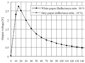
 The graph that the data sheet provided gives a good bird’s-eye view of how to solve the problem. For this fit, It will be accurate about 15-150cm. I just simply plugged in a voltage meter and started taking measurements of the output voltage. I then used logger pro to plot and fit the points.
For this example, I was using the Arduino. One thing to keep in mind is that the arduino only has a 10bit ADC. The voltage of interest for the sharp sensor ranges from about .5-2.7 volts. In this range we only have about 450 points of measurement by the ADC. In order to improve this I set the analog reference to internal which maxes out at 1.1volts. Then used a voltage divider on the sharp sensor’s output so that 2.7+.1 scaled to 1.1 volts.
For the voltage divider, I just used a 20k potentiometer, so R1+R2 = 20k. Vin is 2.8, Vout is 1.1, so R2 needs to be 7857ohms (measure this with your voltmeter.). So the center tab of the pot will be Vout, And the sides will be R1 and R2. It doesn’t matter on your polarity, but make sure that the 7857ohms is what’s connected to ground. Once you’ve wired everything check Vout to ensure the 2.7v output is a little below 1.1v.
I will mention that when the sharp sensor updates, it will make a little ‘bloop’ in the analog voltage output. The signal to noise ratio tends to drop right before and after it updates. You can put a capacitor connected to the micro controller’s analog input pin and connect the other wire of the capacitor to ground. If you need to filter some of the readings, as I did, then I suggest don’t use the capacitor, filter, then do a running average. The method of read ->filter -> running average seemed to work best.
Below is example code for Arduino, and I simplified the equation a bit! I was using a 2.64v to 1.1 voltage divider, but you can just key in your values.
Note: All analogs are on 1.1v! Don’t go above this or you’ll probably fry your chip!
Code for Arduino: (ver ~ 0022)


Thank you – this looks great and as a Mech. Eng, with electric speak as a second language, I appreciate your clear descriptions and explanation. We plan to make a 3D position sensor with these so finding this is a great help.
Glad it helped. I only had one of these sensors, so I don’t know if each one will need its own function fit to be accurate (no clue what the tolerance is). Please share your results.