Nixie clocks
January 16, 2017 6 Comments
Some clocks I’ve made:
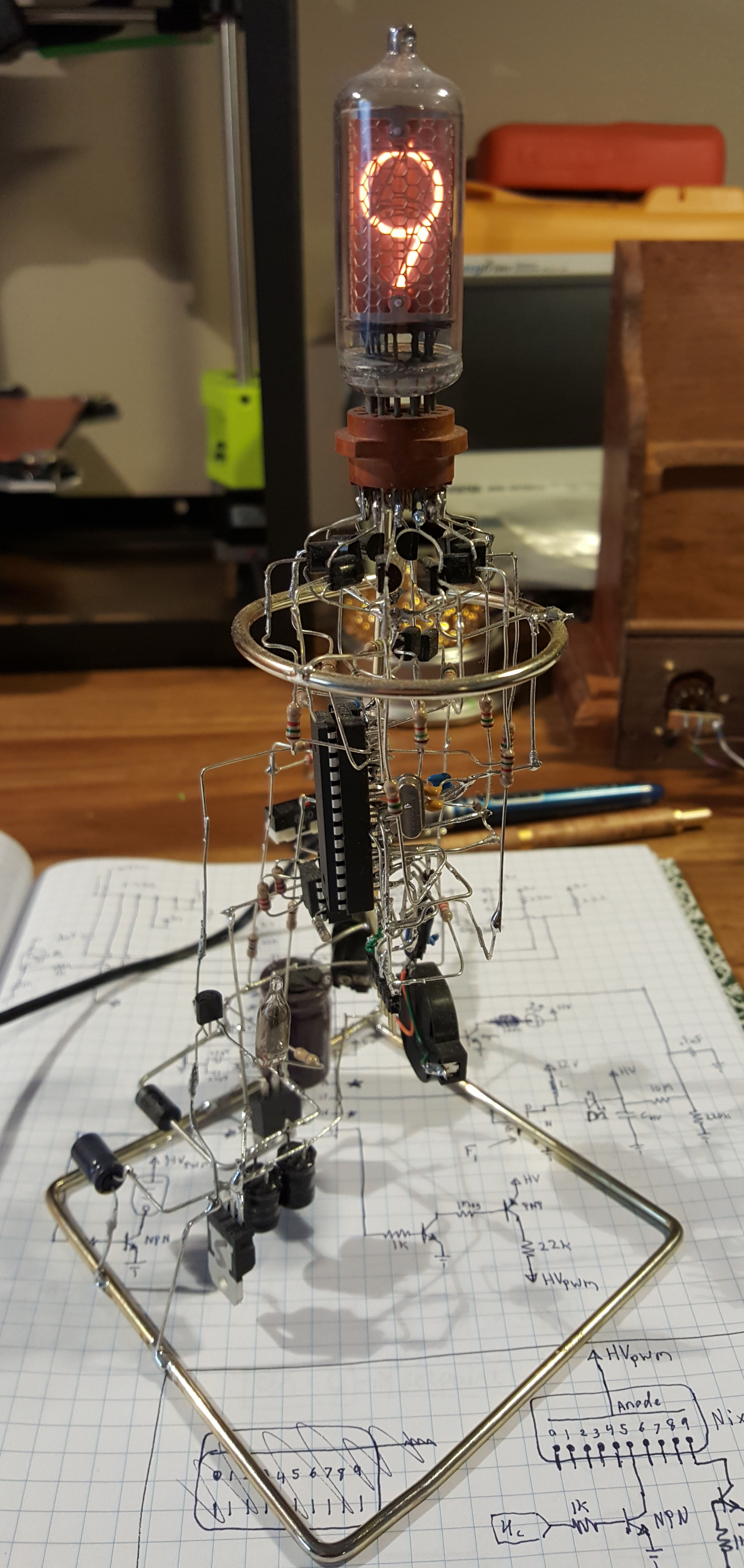
Lethal Nixie Clock

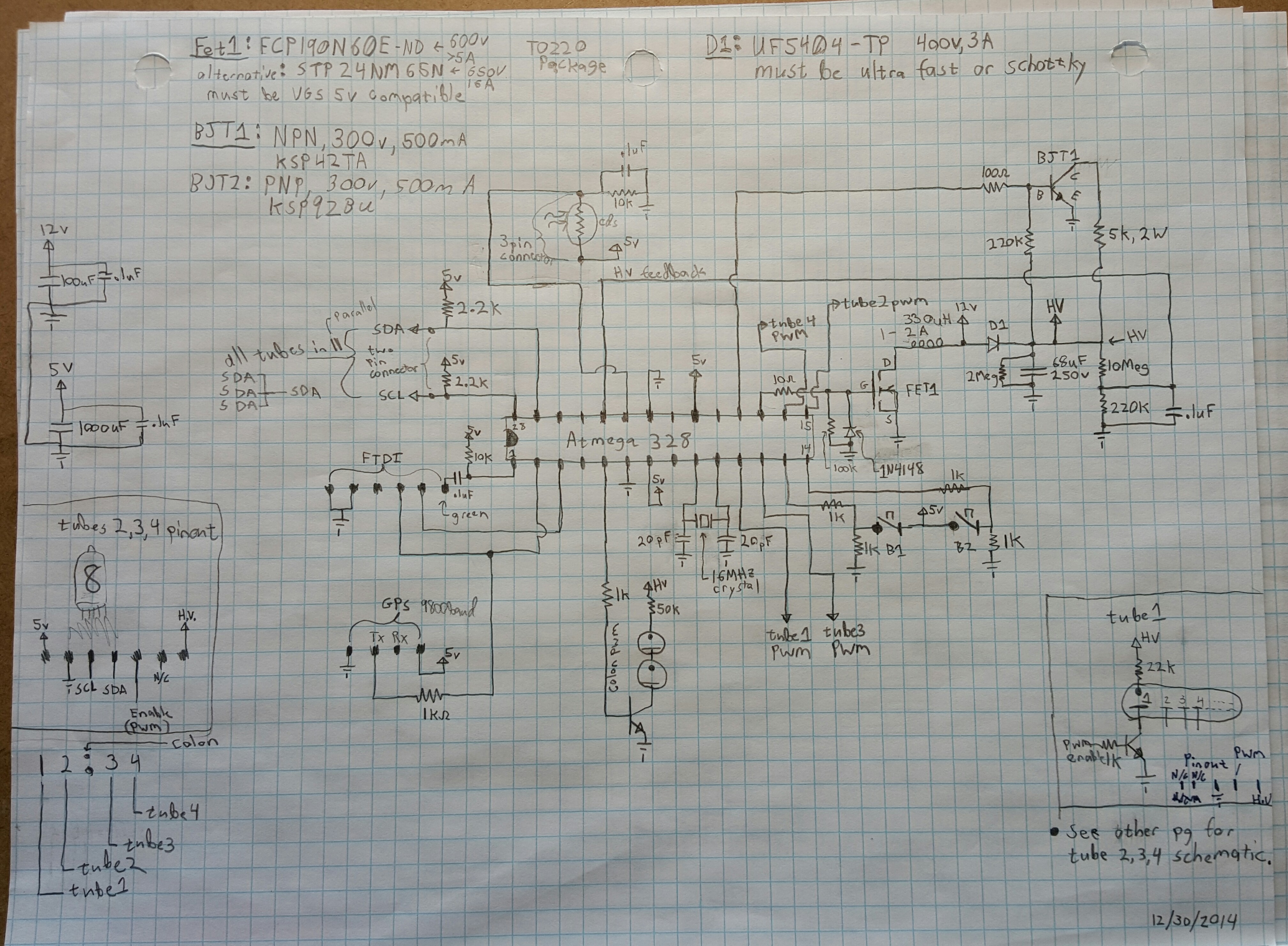
Clock 1 schematic
Clock 1: Single tube Lethal Nixie clock — you know having all the high voltage lines exposed and un-insulated. Inspiration for this design was from this clock. Unfortunately I built mine right after having surgery. I think the painkillers had something to do with the aesthetics… Anyhow I wasn’t electrocuted while building it under the meds…That’s always a plus!
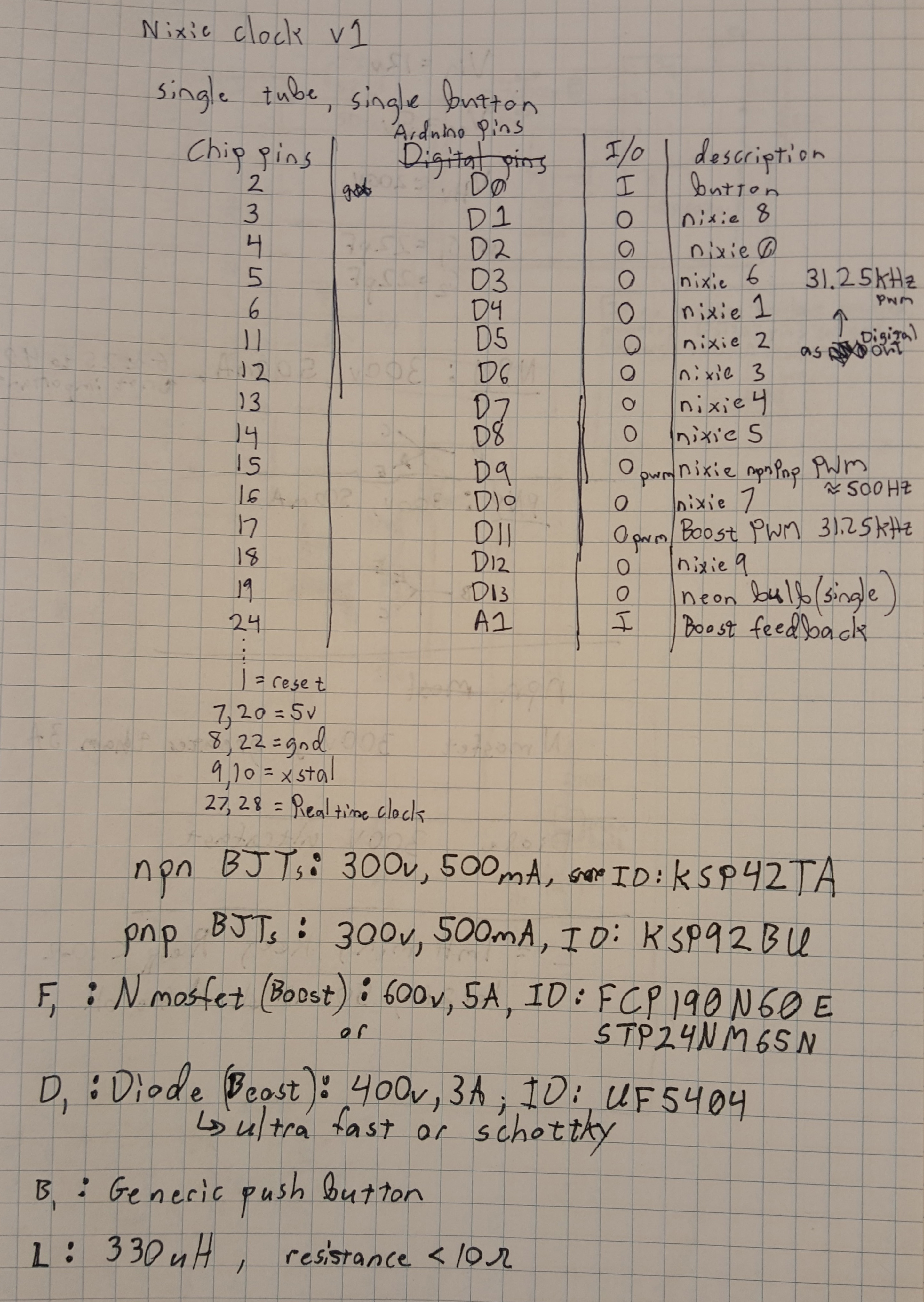
Clock 1 Pinout and key components
ATMEGA 328 arduino with a DS1307 RTC for timekeeping. Basically the arduino pulls time from the RTC then updates IO. During this it’s got a time based ISR that: interrupts the code, measures the high voltage, then makes necessary tweaks to the boost converter duty cycle via a proportional controller. Alright let’s get to me gabbing on about it in the video. I forgot to show how to set the time in the video, here’s a quick video on that. Arduino Code here.
Clock 2 main schematic
Clock 2: Four tube nixie clock. Very similar to the previous clock but uses i2c GPIO port expanders for all the tube outputs, and a GPS instead of a DS1307. This clock just needs some final tube aligning and some buttons to change the time zone! Everything’s implemented on the board/code side. Code for it is here. Just a heads up this is a ‘guide’ to making one, not instructions.
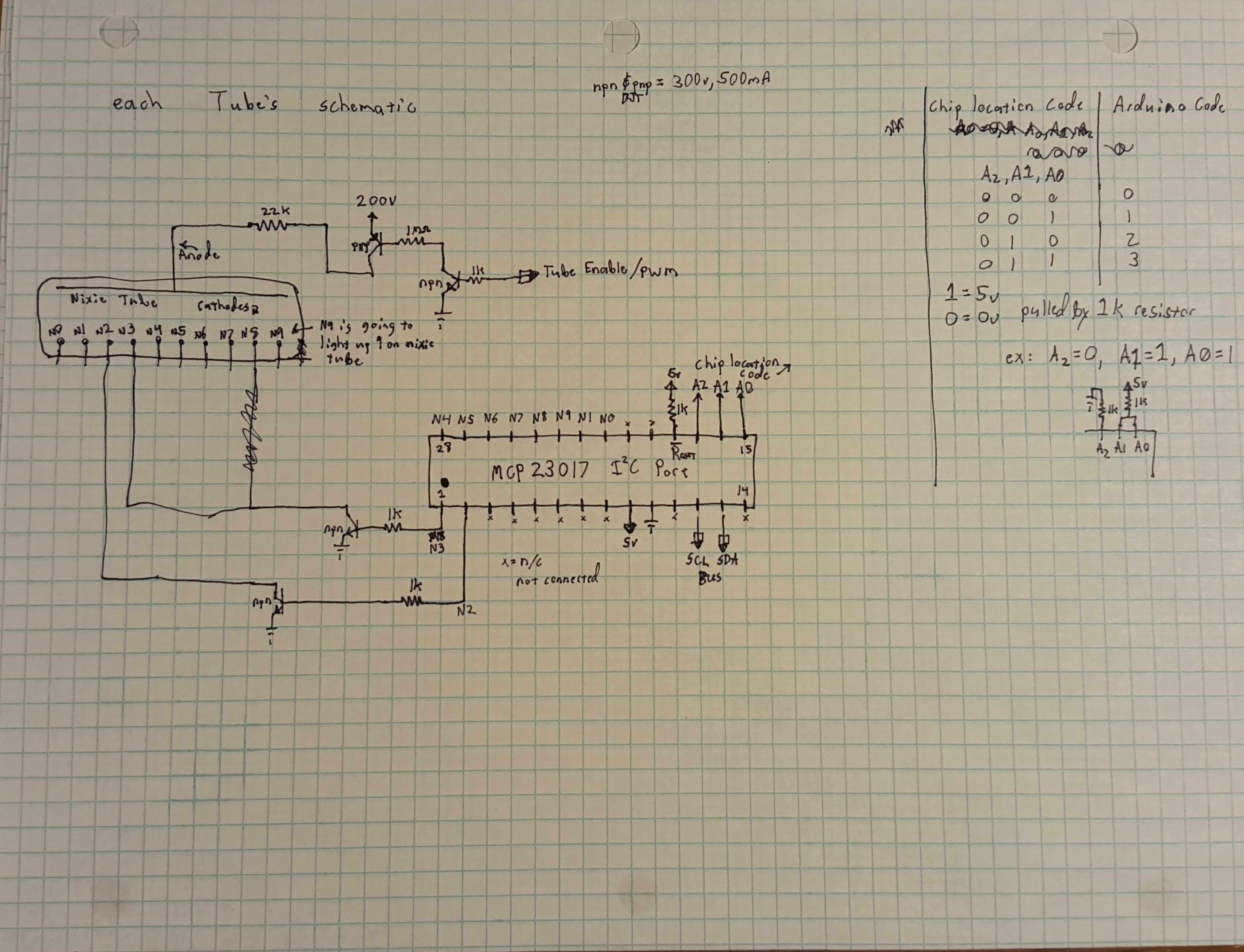
Clock 2 individual nixie tube schematic
The individual nixie tubes have the same repetitive circuit for each cathode, here’s what one cathode

Clock 2 protoboard header layout
looks like (you’ll need to make 10 replications for a tube that needs to display 0-9, for like the tens minutes you’ll only need 0-5 cathodes to work. The gpio expander boards all connect to the same I2c bus. There’s jumpers on the MCP that select the i2c address, these jumpers are different on each tube to allow the microcontroller to control each one individually.Anyway VIDEO PART2, PART3 here. I did a lot of explanation in the video’s, so I’ll keep this post brief.

Clock 2 Pinout mapping of nixie tube
Finally Clock 3 (Not a nixie!):
This is when I look back and think “I really make too many clocks…”, I’ll keep this one brief. This is a clock based on a ~3 inch TFT with touchscreen with Teensy3.1. It generates fractals thanks to a julia2 fractal algorithm I found online. My code randomly tweaks some of the constants that determine shapes/colors in the julia2 algorithm to keep things fresh.
As you can see it graphs temperature, humidity, barometric pressure over a 2 day period. The vertical markers represent 6 hours. The graph auto

Fractal Clock
zooms/offsets each sensor’s data to keep it looking nice with the mins/max displayed at top and bottom per graph. The 3d printed case insulates the insides, so the temperature is a bit high — i need to print one with more vents. Time is set by the touch screen (video doesn’t show that). As you can see I actually made this clock quite some time ago. Source code here.
I did a game of life with this library too. I meant to make a clock where the game of life would randomly get organisms added that would eat away at the time. This code also demonstrates the graph algorithm that auto scales/auto offsets.
Clock 4:
Hey remember that original clock? I also made a kit I had up on ebay for a while. PCB was designed with CircuitMaker, PCB manufactured by OSHpark

Ebay kit of the ‘lethal nixie tube clock’


