Color detection with Arduino for under 5$
May 28, 2011 6 Comments
 Let’s say that you’re working on a project and it needs color detection. This guide will help you make a basic red, blue, green color detector that will decide if an object is present – and the color of the object. A range of up to 6cm is possible with proper guidance tubes! Let’s look at some of the options of completed sensors on the market:
- TCS3200-DB Color Sensor: 60$ + 6$ cable + 10$ cable breakout– Parallax.com
- ColorPAL 20$ – Parallax.com
- Avago ADJD-S311-CR999 – 6$ – sparkfun.com (no breakout yet)
The TCS3200 is a great sensor that I’ve used on Propeller and Arduino based projects, but its 80$ per sensor once shipping is paid! For the ASEE robot we needed two of these and our total budget was 450$! Since we purchased a TCS3200, I decided to reverse engineer it and create my own! It’s a great sensor, but do we really need an adjustable lens with anti reflective coatings? It’s a bit large too…
There are two white LEDs and an array of photodiodes inside. Some of those photodiodes have color filters on them. Pulling certain pins high/low will determine which diode groups are selected — no filter, red, blue, green. The color sensor outputs a square wave and it’s frequency is proportional to the light intensity. There are also frequency multiplication pins which change the proportional constant.
Design:
There are a few different ways to do this, but I’ll cut to the chase and give you what I found to be the best. Let’s use a sensor to measure ambient light, and compare that measurement to measurements with only a powered red LED, blue LED, and finally a green LED. I say ‘sensor’ because there are many different light sensors that will fit the job.
Some of the major pros of this method is that it only needs 3 digital pins and 1 analog pin on the micro controller when using a photoresistor. If you want to use a photoresistor but don’t have analog pins, then use my “Measuring resistance or voltage with 1 I/O” post! This sensor can be built into a very small form factor with decent sampling rates less than 20ms!
Choosing a light sensor – this guide is for a photoresistor:
- Photoresistor – Analog, cheap, and easy to find
it rhymes!This is what I used for this project. - Blue enhanced photodiode – Analog, cheap, look at the TEMT6000 pictures for schematic.
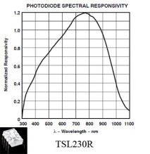
- TSL230R Light intensity to frequency – Digital, fairly cheap. I’ve used these plenty of times.
- TSL235R Light intensity to frequency – Digital, looks small.
- TEMT6000 Ambient Light Sensor – Analog, if you don’t like photoresistors or the digital.
Choosing the LED:
- ‘Piranha’ RGB LED – what I used because we had some sitting around looking for a nibble.
- RGB LED – another LED that would be great.
- Just use 3 separate bright LEDs
The build:
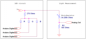
The Piranha RGB LED is a bit different than we might expect. In order to turn on the red LED we’ll need to pull the blue and green pins HIGH, then pull red LOW. Only one LED at a time may be lit, otherwise the LED with the lowest threshold voltage will probably be the only one to light.
This design will use 19mA per sensor. Two sensors may have their LED lines tied together since the Arduino is capable of sourcing/sinking 40mA. Each color sensor’s photoresistor (output) will need a dedicated ADC pin on the micro controller.
Important:
Isolate the LED and photoresistor by using white paper tubes wrapped in a layer of electrical tape. Cut the tubes so that they’re
about 2-3cm long and fit one on the LED and put the other on the photoresistor with a black piece of tape stuck to the back of the resistor. You want to block as much light as possible on the back end of the photoresistor.
Improving results:
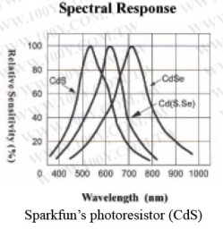
Here’s a way to get a rough calibration: The wavelength for the Piranha is Red: 630nm, Green: 525nm, Blue: 470nm. Now look at the spectral response for your sensor. We can make software corrections to the measurements at the LED’s wavelength. I would suggest doing a constant multiplication to the reading to get all readings to 100%.  The color detection ran well enough that I didn’t need to do this for my project.
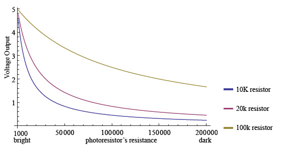
In the schematic above a 10k Ohm resistor was picked mostly because that size worked well for me. The resistor value depends on the light levels and the tube length you’re going to be working with on your robot. A longer tube increase range, but decrease overall light values. This will require a resistor around 20k. Mainly you’ll want to put one of the photodiodes in the tube prior to the build and put it in the environment you’ll be using it in. Here’s a graph that will explain why.
Let’s say that we want the sensor to be very directional and view a far ways away. Since the photoresistor is deep inside a tube, it won’t be exposed to much light. Since it’s probably operating past 100k ohms, if the resistance changes to 150k ohms, then the voltage will hardly change at all when using a 10k grounding resistor. Don’t forget that there are only 1024 segments with the on board 10bit ADC! You’ll want to use a part of the graph which has a large negative slope (left side). The right side of the graph will be difficult for the microcontroller to interpret when using small resistor values. A 100k resistor will have a small negative slope, but it’s distributed all over the graph. If you want to adjust the resistance after the project is already done: just add resistance to the ground pin of the sensor. The ground pin connects directly to the 10k resistor, and nothing else uses it. Remember that resistors in series is just the sum of the individual values.
You could also think of this in terms of curvyness, so curvature will be small, then large, then small. Don’t go past the large value for curvyness. Methods exist to calculate curvyness but not necessary. If you’re interested it’s on page 833 of James Steward – fundamentals of calculus 6th ed.
Alternative designs:
You could use four possibly three photoresistors and have colored filters in front of them. Then a white LED to look for reflectivity. This method is more difficult to calibrate, and would require three to four analog pins with one digital pin for the LED.
Code for Arduino:


I’m going to give this a try thanks!
Have you used the parallax colorpal with arduino by any chance?
And if so, would you have some code to share?
Robbie
Please tell me how it goes!
I haven’t used the color pal, but after skimming the datasheet it doesn’t seem too bad. I’m a bit surprised it’s not i2c or something more stackable… anyway make sure to read the second half of page 6 on the colorpal datasheet (the one written by parallax)
http://vidandpaulbe470.blogspot.com/2011/02/our-code-for-using-colorpal.html
Thanks Moser, your a life saver!
The code from that link is perfect. Worked first time! I’m not great at writing code. I’m more of a cut & paste guy and have learned that way to understand code in general. My main aim with this code is to adapt it to play musical notes according to differing colours that the sensor picks up. I’ll let you know how it turns out when I’ve done it.
robbie! thats my final project idea and im currently struggling with it. did you have any luck with it? im using miniaudicle/ chuck to produce the sounds…
How to coding & interface this sensor with arduino and 16×2 LCD
Pingback: ASEE 2011 Competition | ReiBot.org