Using the TCS3200 with Arduino or Parallax Propeller.
July 6, 2011 13 Comments
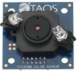
Working on a project which requires color detection, but you don’t want to bother with making your own color sensor? The TCS3200 is a great sensor offering sampling rates much higher than one made with a photoresistor. The main downfall to it is that the TCS3200-DB package from Parallax is very expensive ~ 80$ and more complicated to calculate spectral response compensation. If you’re up for some fun, make your own color sensor!
How it works:
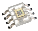
As you can see there is an array of photodiodes with color filters on top. There are four types of filters – red, blue, green, and a clear filter. You may have noticed that there are multiple photodiodes of each color, and this helps reduce bad readings due to non-uniformity of incoming light.
Excluding power, TCS3200 only has 1 output and the rest of the wires are all inputs. The output is a 50% duty cycle square wave with a frequency proportional to the light intensity (irradiance) on the selected filter. There are two pins to divide the frequency of the square wave S0 and S1, and two pins to select the color filter S2 and S3. The chip works from 2.7V to 5.5V, so it’ll work fine with 3.3V or 5V micro controllers.
Wiring:
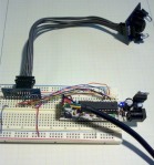
When using the TCS3200-DB with Arduino: Connect Vdd, V, and +5v to the Arduino’s 5V line, Gnd connects to the Arduino’s Ground. All other wires are on the example program.
Program functionality for Arduino:
The program will need to determine if there an object in front of the sensor. If there is an object present, then figure out what color it is. I will be looking at the TCS3200 output’s rising edge to the falling edge, so the less time elapsed means that there is more light. There will be some redundant readings, but this is to help ensure correct detection if anything is moving.
Take a measurement with the LED off, then compare that to a measurement with the LED on (line 53), both using the clear filter. If there was a significant difference then that means that there is an object in front of the sensor. If there wasn’t a significant difference then just return a zero (line 61-64).
Take a clear filter reading and compare it with readings of each color filter, both with the LED on (line 67-72). Then do somewhat of a reverse ratio, since smaller means more light, and pick the largest reading (lines 70 – 96).
Now there will be a serial output of all the ratios and this program simply selects the largest. If you need more accurate readings instead of just the primaries, then I suggest divide the ratio with the spectral response found in the datasheet.

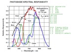
Spectral and pinout from datasheet. Note: if you're using the product from Parallax, use the spectral response from their TCS3200_doc.pdf.
There are plenty of comments in the programs below to help the user get started. there is a detectColor(TCS3200’s output square wave pin) that will return a 0 if nothing is in front of the sensor, 1 for red, 2 for blue, and 3 for green. After each reading it will power off the TCS3200 chip and LED.
I don’t fully support the Parallax Propeller, but I did write a simple program to do basic readings.
TCS3200 for Arduino with line numbers
TCS32000 for Arduino without line numbers
TCS3200 with Parallax Propeller (main.spin)


what distance that sensor can handle to get a proper reading ?
1-2 cm. depends on ambient light. I didn’t play with this sensor a ton saying it was far too expensive for our project.
sorry if my english were not great,
i learn on your code on Arduino. can you give me reason why the pulse how to be limited in 80k ?
Where did you get the 80k number from? The arduino pulsein() is limited to measuring a pulse as small as 10 microseconds which is a 100kHz square wave which is close to your 80k number.
http://arduino.cc/en/Reference/pulseIn
Hello, is possible read the colur in to the format rgb with walue from 0 to 255?
Yes you can do a linear function fit, but don’t expect any sort of accuracy as in some kind light intensity unit due to unknown spectral performance of each component in the optical system
I am EE student as well from Malaysia.I would like to know how does the s2 and s3 and s1 and s4 works actually.. why we need to select the filter at the first place? I thought the TCS 3200 module will automatically change it to voltage or current. Why we need to select the filter and also adjust High and Low for S1 to S4?
Some of the pins select the color filter used on the light sensor output. Other pins select the sensitivity of the light sensor. The sensor has 1 output which is why u need to cycle through the color filters it’s using
Hey, I am Jeff, from Malaysia, I doing similar project and I wish I can learn from you.. I have a question, that is, how does the s2 s3 works? I thought we can get the value automatically when compared. How about s1 and s4? why we need to change s2 and s3 to high and low? arent is automatically detect?
Hi, we are doing our project with gy-31 colour sensor. We have to sense red, yellow and blue and run the robot in 3 different path according to the colour detected. We are using arduino uno. Please help in writing the code. We have a very limited time to complete the project
hello Moser, do u have a picture in which i can see how i can connect this sensor in arduino leonardo? romeo V2 exactly?
I don’t. You can edit the code and give it a shot! Btw this sensor is very pricy, you may want to look around for alternatives or make your own
I see you don’t monetize your website, don’t waste your traffic,
you can earn additional bucks every month because you’ve got high quality
content. If you want to know how to make extra money,
search for: best adsense alternative Dracko’s tricks