Venturing into 250cm quadcopters
November 17, 2014 2 Comments

My quadcopter
Hey all sorry it’s been so long! I promise I’ve got a tutorial on the way for a super simple and easy to build nixie clock that I’ve designed. Anyway I thought I’d share my quadcopter build. This isn’t a tutorial! I’ve included a BOM at the end, and I encourage anyone who’s experienced in putting electronics together to give it a shot! If you’re interested but intimidated, I’d be up for building and tuning a quadcopter for you for a very reasonable price! If you want to get into this hobby, I highly recommend you to buy a cheap toy quadcopter like this one and learn to fly — I guarantee it will save you money and frustration in the long run. I’m also rank 1 jet/heli pilot in BF4 and I can say it flies similar to a small chopper when using the FPV system (wireless camera First Person) :P
Inspiration
Check out some other racing mini quads
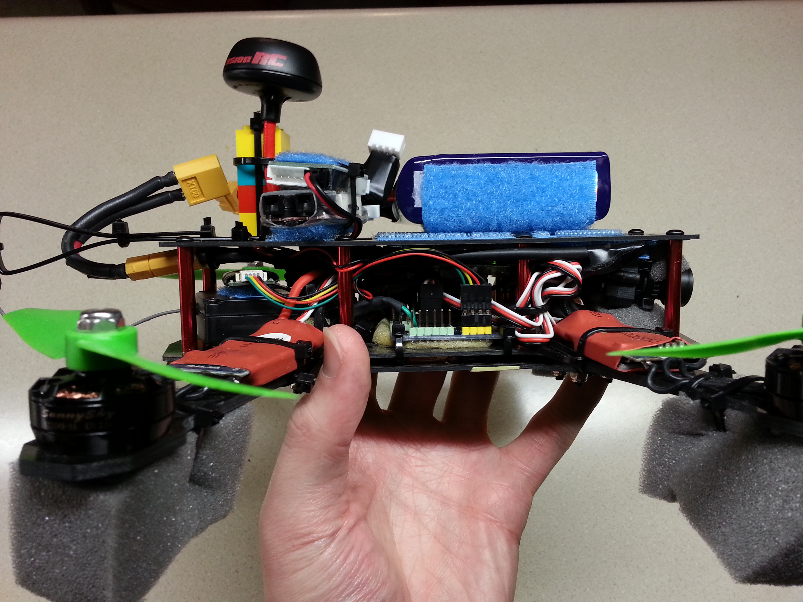
Better view of electronics and camera
BOM
The BOM is what/where I bought parts. Don’t forget that multirotors need ESCs that don’t do any input filtering. Get an ESC (like in the BOM) flashed with SimonK firmware or an equivalent. Check out my youtube video’s description for latest parts.
Overall my quad is flying like an absolute champ! Unlike the QAV250, it doesn’t have a battery hanging way out the rear, which has caused the QAV250 to have some notoriously bad flight characteristics due to poor weight distribution. The only thing I’d change are the 20A escs which are overkill on 3s maybe get a 12A esc, but a 20A esc compatible with a 4s battery would really put this quad into overdrive — I’ve read the motors can handle 4s but may fail if pushed to hard.
Some terms
What is this ‘s’ mentioned above? It stands for the number batteries in series in a battery pack: 4s = 4*4.2v = 16.8v, 3s = 3*4.2 = 12.6v. A fully charged lipo = 4.2v per cell.
Also in my BOM I have a high ‘C’ battery. C determines how much current the battery is rated for. To find this max current take the C*mAh/1000 = max continuous amps. So a 1300mAh, 45-90C battery can do 45*1300/1000 = 58.5 amps continuously, but can handle a spike of 90*1300/1000 = 117 amps. In this field a spike is generally less than 10 or 5 seconds.